Helloworld In Embedded Systems

I'm an Embedded system developer and IoT solution architect, PCB Designer
Unlike other stacks with their peculiar languages whose first project might be printing "Hello world" over the console or terminal, it is quite different from what we are going to learn today. We will be blinking an LED using the C programming language on the ARM cortex-m4 STM32F407VETx microcontroller based breakout board, this could be replicated on ST's Nucleo or Discovery board of choice with little or no modification. Blinking an LED in embedded systems could be likened to conventional "Hello world" in other tech stacks.
Yeah, I know you are enthusiastic to get started and figure out what this project entails. That is totally fine, I mean I was once in your shoes some years ago, grab a coffee let us get started.
What is Embedded system?
An embedded system is a microprocessor- or microcontroller-based system of hardware and software designed to perform dedicated functions and tasks. It is the integration of firmware onto a hardware device with the aim of performing specials task, or specific functions. you can read more on this here https://www.tutorialspoint.com/embedded_systems/es_overview.htm
Things you need for this project:
- LED
- Jump wires
- Breadboard
- ST-Link V2 (External programmer)
- STM32F407VETx breakout board
- 1 x Resistor 100 ohms
- ST CubeIDE software
- STM32F407 datasheet and reference manual
Before we continue let us have a look at the stm32 microcontroller unit(MCU) in use here. The STM32F407VETx MCU is one of the microcontrollers produced by ST. The STM32F407xx family is based on the high-performance ARM® Cortex®-M4 32-bit RISC core operating at a frequency of up to 168MHz. The Cortex-M4 core features a Floating point unit (FPU) single precision which supports all ARM single- precision data-processing instructions and data types. While working with this MCU might look a bit complex, the truth is it is not at all. It has more to do with shifting ones and zeros into addressable registers to enable or disable desired functionality. Below is the block diagram of our MCU.
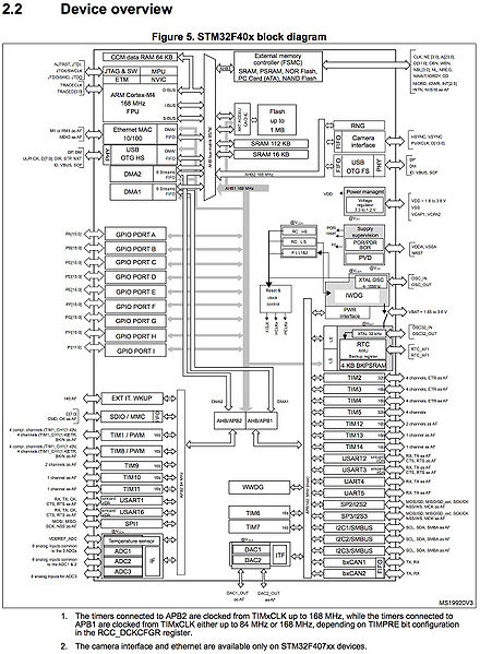
Considering our block diagram, we can see that our GPIO Port peripherals (GPIO Port A, GPIO Port B etc.) are all connected to the AHB1 bus which runs at maximum speed of 168MHz. For this tutorial, we are going to use the CMSIS(Common Microcontroller Software Interfaced Standard) library from ARM technology.
So our first step will be to open our cubeIDE and and create a new project by doing the following:
Navigate to file and click on it
Click on 'new'
stm32 project
Select your specific board or MCU type
Give your project a name, mine is "TEST-TEST"
Select 'STM32Cube' under "target project type", then click finish.
The next step is to find our "main.c" file in our newly created project and double click on it.
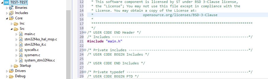
So we go ahead and delete all our initializations and comments that came with our 'main.c' file, then include our device specific header file, this informs our CMSIS library the exact type or family-type of MCU we are working with e.g "#include stm32f4xx.h" followed by our main function.
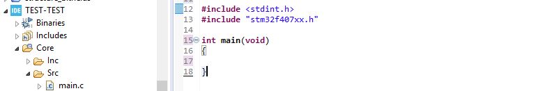
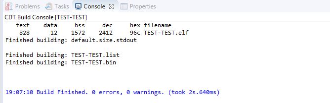
Easy right? go ahead and compile this code just to make sure all is in good shape, right-click on the project and click on build, we should get a message on the console saying the build was successful.
Now we enable the clock access to our preferred GPIO port, say GPIO A. Navigating through our stm32f4 reference manual, this can be done in the Reset and Clock Control(RCC) register of our microcontroller, RCC AHB1 peripheral clock enable register (RCC_AHB1ENR) to be more precise.
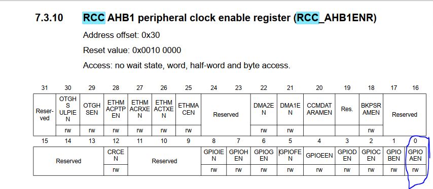
let us go ahead and enable the clock for GPIOA by writing bit '1' to the '0'th bit position of the RCC AHB1 peripheral clock enable register (RCC_AHB1ENR).
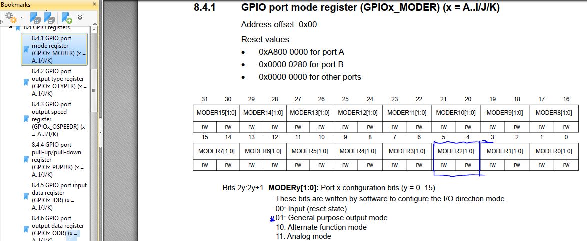
Then we proceed to the GPIO port mode register, to configure our desired pin as each port is entitled to 16 configurable pins, which ranges from pin 0-15 in this case since we have chosen GPIO PORTA our selection would range from PA0 - PA15. We would configure this desired pin to be in its output mode as to be able to drive our LED. It is important to check your development board's schematic to be sure that your desired pin is free and is not tied to serving any other purpose on your board. So we navigate again to our reference manual to find out how to set our desired pin to output mode.
My interest is PA2, yours might differ if your PA2 is serving any other serious purpose on your board.
Since I want to configure PA2 to output mode, I will write bit '0' and '1' to the 5th and 4th bit positions of the register respectfully i.e. MODER2[1;0].
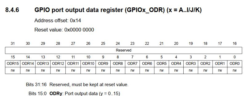
Our job is almost done, the next step will be to set and clear the 2nd bit position of the GPIO port output data register (GPIOx_ODR), in order to make PA2 high and low thus blinking our LED attached to it.
So let us go ahead and do this in our code. It is important to note that without any significant delay we will not be able to see our LED blink therefore we need some sort of delay, in-between turning our LED on and off. The best way to have an efficient delay generally in embedded systems, is to utilize the built in timer peripheral(s) in our MCU. This tutorial won't cover that, we would rather use a for loop to cause a significant delay.
Here is the entire code;
#include <stdint.h>
#include "stm32f407xx.h"
int main(void)
{
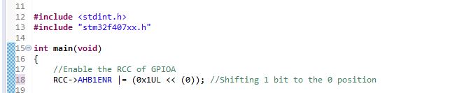
//Enable the RCC of GPIOA
RCC->AHB1ENR |= (0x1UL << (1)); //Shifting 1 bit to the 0 position
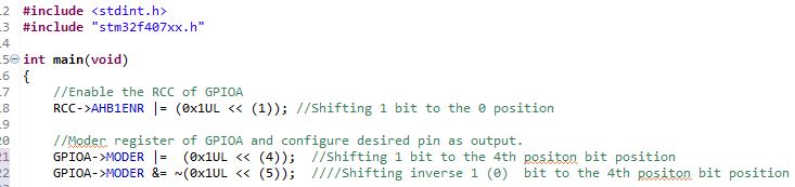
//Moder register of GPIOA and configure desired pin as output.
GPIOA->MODER |= (0x1UL << (4)); //Shifting 1 bit to the 4th positon bit position
GPIOA->MODER &= ~(0x1UL << (5)); ////Shifting inverse 1 (0) bit to the 4th positon bit position
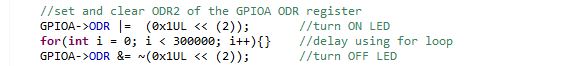
//set and clear ODR2 of the GPIOA ODR register
GPIOA->ODR |= (0x1UL << (2)); //turn ON LED
for(int i = 0; i < 300000; i++){} //delay using for loop
GPIOA->ODR &= ~(0x1UL << (2)); //turn OFF LED
}
build the project again in order to have the entire code compiled. now let us load the .bin file into our MCU. Plug the ST-Link V2 into your PC and connect it to your development board using jump wires in this arrangement.
ST-Link V2 Pin ====== Development board Pin
SWDIO ======= ==> SWDIO
GND ====== ==> GND
SCLK ====== ==> SCLK
NRST ====== ==> NRST
Right click on your project on the IDE then click on "Run As" select "STM32 Cortex-M C/C++ Application", that will be all. Go ahead and connect your LED and resistor on your bread board in this arrangement below.
Wrapping up
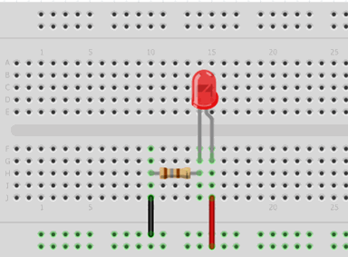 Connect the red jump wire, the anode pin of the LED to PA2 or your configured output pin then connect the black jump wire to the GND pin on the board. Press the reset button on your development board, you should see your LED blinking.
Conclusion
That is all for this article, if you encounter any problem please do well to reach out to me via the comment section. Thanks for reading, see you next time.
Twitter: https://twitter.com/AghaKingsley3
Github: https://github.com/spizytek
#programming #Tech #embeddedsystems
REFERENCES
- https://www.st.com/en/development-tools/

